
Nodal analysis with dependent sources
Updated
Nodal analysis with dependent sources works almost exactly like it does with independent sources. You write a KCL equation at each node, treat each dependent source like any other source, and add one extra equation that writes its controlling voltage or current in terms of the node voltages.
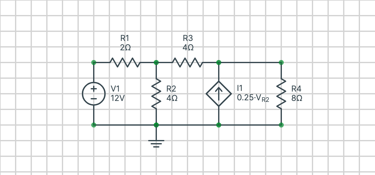
The circuit below is the first worked example on this page. You can edit it, or draw your own, then solve it step by step.
What is a dependent source?
A dependent (or controlled) source is a voltage or current source whose value depends on a voltage or current somewhere else in the circuit. It's drawn as a diamond. There are four kinds:
| Source | Its value | Units of the gain |
|---|---|---|
| Voltage-controlled voltage source (VCVS) | volts | none (V/V) |
| Current-controlled voltage source (CCVS) | volts | ohms (V/A) |
| Voltage-controlled current source (VCCS) | amps | siemens (A/V) |
| Current-controlled current source (CCCS) | amps | none (A/A) |
Here is the voltage across some component and is the current through it. They are the controlling voltage and current, and they're the only new thing nodal analysis has to deal with.
How to do nodal analysis with dependent sources
- Choose a reference node and label the voltage at every other node: , , and so on.
- Write the controlling quantity in terms of node voltages. A voltage across a component between nodes and is . A current through a resistor from to is .
- For a dependent current source, include its current in the KCL equations at the two nodes it connects, just like an independent current source, using the expression from step 2.
- For a dependent voltage source between a node and the reference node, it simply sets that node's voltage. Between two non-reference nodes, it makes a supernode: write one KCL equation for both nodes together, and use the source as a constraint between them.
- Substitute and solve. Replace the controlling quantity in every equation, which leaves only node voltages as unknowns, then solve the equations (by substitution, or as a matrix).
- Check your answer. Work out the controlling quantity and the dependent source's value, and make sure KCL holds at a node you didn't use.
The gain of a dependent source isn't always unitless. A VCCS with a gain of produces for every volt of , so its gain is .
Example 1: a voltage-controlled current source
In the circuit at the top of the page, a source sets node 1, resistors connect nodes 1, 2 and 3, and a dependent current source pushes a current of into node 3. The controlling voltage is the voltage across , the resistor from node 2 to the reference node. Find the node voltages.
Step 1: label the nodes
The bottom wire is the reference node, . The voltage source fixes node 1:
which leaves and as the unknowns.
Step 2: write the controlling voltage in terms of node voltages
connects node 2 to the reference node, with its + end at node 2, so
Step 3: write KCL at each unknown node
Adding up the currents leaving each node, at node 2:
At node 3, the dependent source pushes into the node, so it's subtracted:
Step 4: substitute and solve
Replace with , then multiply the first equation by 4 and the second by 8:
As a matrix:
Adding the two equations gives , so
Step 5: check
The controlling voltage is , so the dependent source supplies . Out of node 3, flows through and through , which adds up to the coming in.
Open Example 1 in Circuitsteps to see every step, including the branch currents and how the matrix is solved.
Example 2: a current-controlled voltage source between two nodes
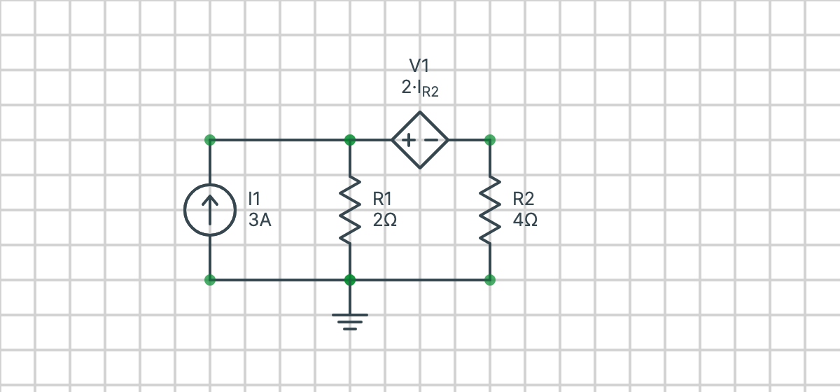
Here a current source feeds node 1, () connects node 1 to the reference node, and () connects node 2 to the reference node. Between nodes 1 and 2 is a dependent voltage source of volts, + at node 1, where is the current down through .
Step 1: spot the supernode
The dependent voltage source sits between two non-reference nodes, so you can't write KCL at node 1 or node 2 on its own: the current through the source is unknown. Instead, nodes 1 and 2 together form a supernode.
Step 2: write the controlling current in terms of node voltages
Step 3: write the constraint and the supernode's KCL equation
The source sets the difference between the two node voltages:
Adding up the currents leaving the supernode, where the source's current comes in:
Step 4: substitute and solve
Step 5: check
The controlling current is , so the source's voltage is , which matches . The through and the through add up to the from the current source.
Open Example 2 in Circuitsteps to see it solved step by step.
Common mistakes
- Forgetting the control equation. The controlling quantity is a new unknown. Without an equation for it in terms of node voltages, you'll have more unknowns than equations.
- Getting the controlling quantity's sign wrong. is measured from the + end to the − end shown on the circuit, and in the direction of its arrow. Swapping them flips the sign of the source.
- Treating the source's value as a number. A dependent source's value changes with the circuit. Keep it as an expression until you've solved for the node voltages.
- Writing KCL at each node of a supernode. When a voltage source (dependent or not) connects two non-reference nodes, its current is unknown. Write one KCL equation around both nodes instead.
- A controlling current through a voltage source. Node voltages can't give you the current through a voltage source directly. Add that current as an extra unknown, or use mesh analysis, where every branch current comes from the mesh currents.
Nodal or mesh analysis?
Nodal analysis is usually easiest when the dependent sources are current sources, or when the controlling quantity is a voltage. Mesh analysis is usually easiest when they are voltage sources, or when the controlling quantity is a current. Either method gives the same answers. Circuitsteps can solve a circuit both ways, so you can compare: try the nodal analysis calculator or the mesh analysis calculator.
Frequently asked questions
How do you handle a dependent source in nodal analysis?
Treat it like an independent source when you write the KCL equations, then add one more equation that writes its controlling voltage or current in terms of the node voltages. Substitute that equation in and solve as usual.
What do you do with a dependent voltage source between two nodes?
Put both nodes in a supernode. Write one KCL equation for the supernode as a whole, and use the source as a constraint: the difference between the two node voltages equals the source's value, written in terms of the node voltages.
What if the controlling current flows through a voltage source?
Node voltages alone can't give the current through a voltage source, so either add that current as an extra unknown (modified nodal analysis), or use mesh analysis, where every branch current is written from the mesh currents.
Can dependent sources be used with mesh analysis too?
Yes. With mesh analysis you write the controlling quantity in terms of the mesh currents instead. Circuitsteps can solve a circuit with dependent sources using either method and shows every step.